- en
THERMAL STORAGE SYSTEMS
Series "Trieste"
Thermal Storage Systems


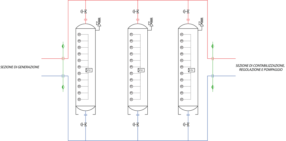
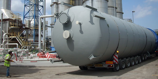
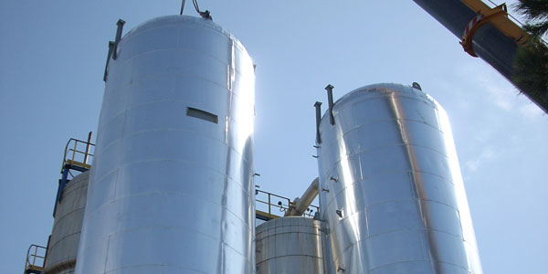
Heat storage systems designed and specialized in hot/overheated water district heating networks made-up of 1 to 8 tanks in parallel. Up to 250 m³ capacity tanks are transportable, even if as special cargo. Beyond this limit they will be built on site. The system comes complete with shut-off valves, control and safety devices, as well as the electrical control panel, regulation, monitoring and data transmission, including provision for remote control and integration on the supervisory systems via existing free and unified protocols.
The most appropriate application, and above all most useful, happens to be in systems where it is advisable or even necessary to stabilize power peaks and use the energy produced in off-peak hours to be used during full peak ones.
- Mod. Trieste 1: hot-water networks
- Mod. Trieste 2: overheated water networks
- Thermal power: 1.5 to 115 MWt
- Volumetric capacity: 50 to 2500 m3
- District Heating max Temperature: 135 ° C.
- Max pressure:16 barg
- Certifications: CE / PED
Range
Mod. Trieste
Hot water Thermal Storage Systems (TRIESTE 1) or overheated water (TRIESTE 2) for district heating networks.
| POS. | Model |
Hot/overheated water tanks # |
Capacity (m³) |
STORABLE POWER Hot water (MWt) |
STORABLE POWER overheated water (MWt) |
Design Temp (°C) |
Hydraulic Design |
|---|---|---|---|---|---|---|---|
| 112 | Trieste 1/2 - 50 | 1/1 | 50 | 1,5 | 2,5 | 100/135 | PN6÷PN16 |
| 113 | Trieste 1/2 - 100 | 1/1 | 100 | 3 | 5 | 100/135 | PN6÷PN16 |
| 114 | Trieste 1/2 - 150 | 1/1 | 150 | 4,5 | 7 | 100/135 | PN6÷PN16 |
| 115 | Trieste 1/2 - 200 | 1/1 | 200 | 6 | 9 | 100/135 | PN6÷PN16 |
| 116 | Trieste 1/2 - 250 | 1/1 | 250 | 7 | 12 | 100/135 | PN6÷PN16 |
| 117 | Trieste 1/2 - 500 | 1/2 | 500 | 15 | 25 | 100/135 | PN6÷PN16 |
| 118 | Trieste 1/2 - 1000 | 2/4 | 1000 | 30 | 50 | 100/135 | PN6÷PN16 |
| 119 | Trieste 1/2 - 1500 | 3/6 | 1500 | 45 | 70 | 100/135 | PN6÷PN16 |
| 120 | Trieste 1/2 - 2000 | 4/8 | 2000 | 60 | 90 | 100/135 | PN6÷PN16 |
| 121 | Trieste 1/2 - 2500 | 5/10 | 2500 | 75 | 115 | 100/135 | PN6÷PN16 |

Working condition
| HOT WATER | SUPERHEATED WATER | COOLING | |
|---|---|---|---|
|
THERMAL DESIGN DISCTRICT HEATING CIRCUIT |
90/65°C | 115/65°C | 7/11°C |
|
MECHANICAL DESIGN DISCTRICT HEATING CIRCUIT |
PN16÷PN25 | PN16÷PN25 | PN16÷PN25 |
|
THERMAL DESIGN SUBSTATIONS SECONDARY CIRCUIT |
85/55°C | 85/55°C | 14/8°C |
|
NOMINAL PRESSURE LOSS SUBSTATIONS PRIMARY AND SECONDARY CIRCUITS |
10/3 w.c.m. | 10/3 w.c.m. | 10/3 w.c.m. |
|
FLUID SPEED DISCTRICT HEATING CIRCUIT |
0,5÷2 m/s | 0,5÷2 m/s | 0,5÷2 m/s |
| CENTRAL CONDUIT PUMPS HEAD | 0,5÷9 bar | 0,5÷9 bar | 0,5÷9 bar |
| PRESSURE LOSS POWER PLANT INNER CIRCUIT | 0,5÷1,5 bar | 0,5÷1,5 bar | 0,5÷1,5 bar |

